WiFi hacking gadget: Ghost ESP on ESP32 (Flipper Zero)

Intro
I recently got a Flipper Zero, which has lots of features related to Bluetooth, sub-GHz frequencies, NFC, RFID, IR and more. However, it lacks capabilities related to WiFi.
Fortunately, Flipper has some input pins on the top side (general purpose input/output, GPIO), consisting of power supply pins and I/O pins. It is possible to attach external modules to it and extend its capabilities, creating the possibility of WiFi hacking with it.
Dozens of different pre-built modules are sold on the market and provide advanced features such as WiFi attacks, GPS functionality, signal jamming, custom sensors, improved card readers/writers, etc. The most famous is the WiFi devboard for Flipper, which adds WiFi capabilities and has lots of features, such as sniffing, evil portal attacks, spoofing, packet monitor, AP scanning and much more.
Instead of buying a module, which can be really expensive depending where you live, we can buy some electronic pieces and build our own custom module. In this text I’ll describe the process I followed to make a WiFi+Bluetooth module for Flipper Zero with an ESP32 microcontroller for around $5.
ESP32
The ESP32 is a microcontroller that is used to do a number of different tasks. It is commonly used in IoT to manage sensors, control hardware and communication, since it has built-in WiFi and Bluetooth capabilities, is really cheap (around $3 on AliExpress) and has low energy consumption.
It can be programmed to interact with its pins — which, in this case, will be connected to the Flipper Zero’s GPIO pins — with Arduino IDE, MicroPython and other platforms, and can communicate directly with smartphones and computers via WiFi, Bluetooth or USB.
In our case, it will be used in addition with a specific firmware that has the WiFi hacking features we are looking for, along with a Flipper Zero app to control it. Note that it is possible to use the ESP32 for this kind of attack without the Flipper Zero, as it can be controlled via USB or Bluetooth. But using Flipper makes our life a bit easier.
There are plenty of ESP32 models out there, some with fewer pins (ESP32-C3), some with more, some with an external antenna connector (WROOM32U), some with USB-C, etc. I used the standard model ESP32-WROOM32 with 30 pins. This should work with most of them. See the compatibility list here.

The software
For this project I used Ghost ESP, an open-source firmware written for ESP32 for wireless network exploration and security testing.
Among its features, it can do Wi-Fi and BLE (Bluetooth Low Energy) analysis, packet capture, beacon generation, and GPS-enabled wardriving. It supports custom captive portal attacks, network device management, security testing, and includes fun features like games and RGB visuals (if your ESP board supports).
There are other firmwares such as Marauder, which is the most commonly used and works pretty well. I tested both and they’re nearly identical for the main type of attacks. Ghost ESP claims to have more features, but the difference is not that significant in my opinion.
Flashing the firmware
1. Flashing with Ghost ESP web flasher
There are many different ways of flashing the Ghost ESP firmware into the ESP32 board. The easiest one is using the web flasher tool by Ghost ESP itself. For that, simply open the website, plug the ESP32 into the computer via USB and select the board. In our case, it is the ESP32 generic. Then, just click “flash” and the browser will prompt us to select the correct serial port. In my case it is the only one shown.

After that, don’t touch the ESP32 or the USB cable to prevent data corruption and just wait until the firmware is flashed. Once you receive the success message, you can unplug the ESP32 from the computer and the job is done.

2. Flashing with Flipper Zero
It is possible to flash the firmware into the ESP32 using the Flipper Zero itself, with the ESP Flasher Flipper app. If you already did it with the web flasher, just skip this part.
To flash it with Flipper, first download the ESP Flasher Flipper app, either from the Flipper store website, or moving the .fap file from the computer to Flipper SDCard/apps (both with the Flipper connected to the PC via USB, with the software qFlipper), or the Flipper app on mobile device (with the Flipper connected to the device via Bluetooth).
Once ESP Flasher is installed on Flipper, open it in Apps/GPIO/ESP Flasher so that it creates the required folders in the filesystem.

Download the the latest Ghost ESP firmware files. This should be a zip file for the ESP platform you’re using (in my case, esp32-generic.zip), with the files bootloader.bin, Ghost_ESP_IDF.bin and partition-table.bin. Move those three .bin files to SDCard/apps_data/esp_flasher/.

Now, it’s time to connect the ESP32 to the Flipper. For this, you can use wires, a breadboard with jumpers or anything that does the job. At first, I used four jumpers directly between the Flipper and the ESP board — two for power and two for I/O. After that, I soldered everything onto another board, as I’ll show later.
The connections should be:
+-------+--------------------+
| ESP32 |    Flipper Zero    |
+-------+--------------------+
| 3V    | 3V3 (pin 9)        |
| GND   | GND (pin 18 or 11) |
| RX    | TX  (pin 13)       |
| TX    | RX  (pin 14)       |
+-------+--------------------+
So the pins for energy, 3V3 and GND, should be connected normally between ESP32 and Flipper. And the RX (receive) and TX (transmit) should be switched. The ESP RX should be connected to the Flipper TX and vice-versa. Once you connect 3V3 and GND, the LED on the ESP32 should turn on.

Once everything is connected correctly, we now need to enter bootloader mode on ESP32. To do that, hold the BOOT button, then press the EN button (can be labeled as “RESET” in some ESP versions), release the EN button, and then release the BOOT button.

Now open the ESP Flasher app on Flipper and select “Flash ESP”. It will show you some memory addresses, asking to select some files.

The files we need to select are the bootloader.bin, the partition-table.bin and Ghost_ESP_IDF.bin, which is the firmware. These are the files present in the esp32-generic.zip we’ve downloaded from the Ghost ESP repository before.

The files must be loaded like this:
+----------------------+---------------+
|        Offset        |     File      |
+----------------------+---------------+
| Bootloader (0x1000)  | bootloader    |
| Part Table (0x8000)  | partitions    |
| Firmware A (0x10000) | Ghost_ESP_IDF |
+----------------------+---------------+
After that, just hit “[>] FLASH” and wait. It should display a message “Finished programming”. When it shows that message, simply disconnect the ESP32 from Flipper and the job is done.

Using the Ghost ESP
Now that we have successfully installed the Ghost ESP firmware into the ESP32 board, we can control our ESP32 in many different ways, even with only a smartphone (provided that you have a power supply for the ESP chip). For this, we’ll download the Ghost ESP Flipper app and send it to the Flipper folder SDCard/apps/GPIO/ with qFlipper. You can then open the app in Apps/GPIO/[ESP32] Ghost ESP.

Connecting the ESP to Flipper
To use our new gadget, we need to connect it to Flipper again, with the same schema we used earlier to flash the firmware.
+-------+--------------------+
| ESP32 |    Flipper Zero    |
+-------+--------------------+
| 3V    | 3V3 (pin 9)        |
| GND   | GND (pin 18 or 11) |
| RX    | TX  (pin 13)       |
| TX    | RX  (pin 14)       |
+-------+--------------------+
Once it is connected, we can choose WiFi on the Ghost ESP Flipper app and use all its features. You can take a look at the documentation to see all the features it has. As an example, I’ve used the “Scan AP” function, and it has detected lots of access points nearby.

Soldering it into a PCB protoboard
To make it look a bit better, I soldered it onto a PCB protoboard a right-angle pin header.


Since the RX and TX pins are switched, and the 3V3 and GND pins are not “aligned”, it’s necessary to do some soldering behind the board. I used some jumpers I had here.

After soldering everything, I got this:

The result was pretty good; it was now ‘plug-n-play,’ with no need for large jumpers that disconnected at the slightest movement.
But I was watching some videos about 3d pens and I decided to buy one and try to build a little case for this.

After some minutes learning how to adjust and use this, I was able to make a little “plate”.

Unfortunately I ran out the purple filament and had to use the orange one, and the finish was quite rough. The result was this terrible thing that looks like Courage the Cowardly Dog:

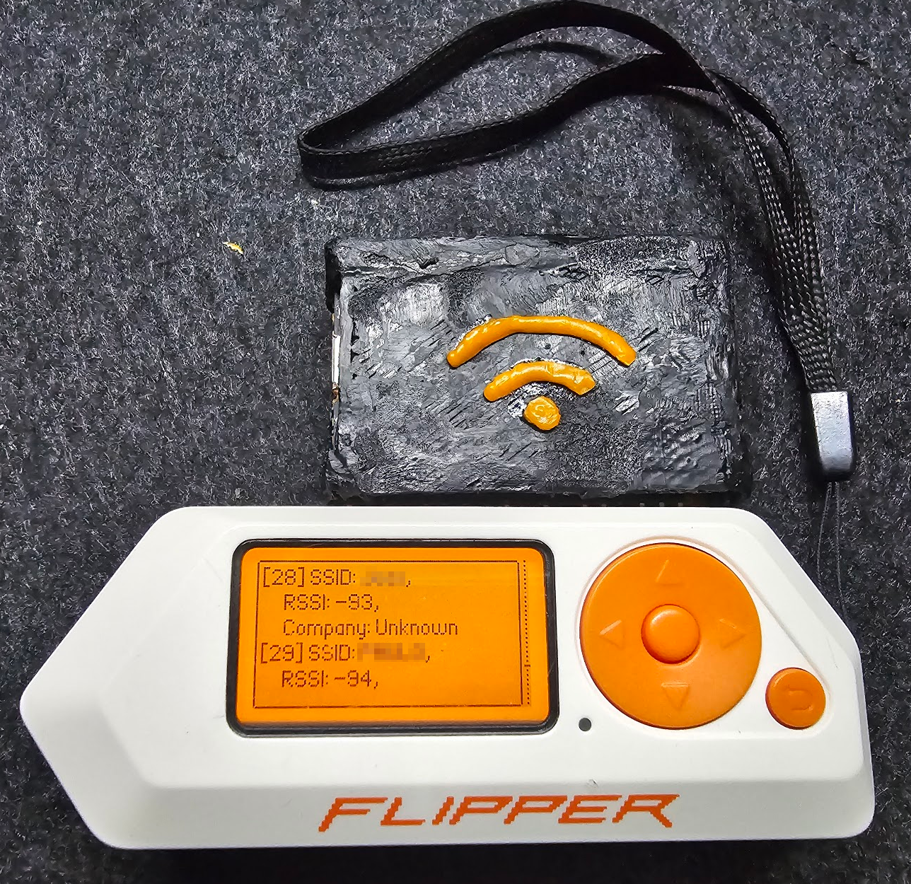
After playing a bit with the 3d pen and learning other techniques for 3d modeling with it, I was able to do something slightly better.

This is the final result: